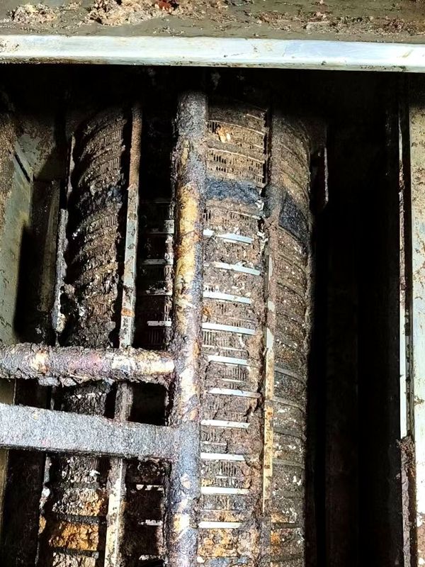
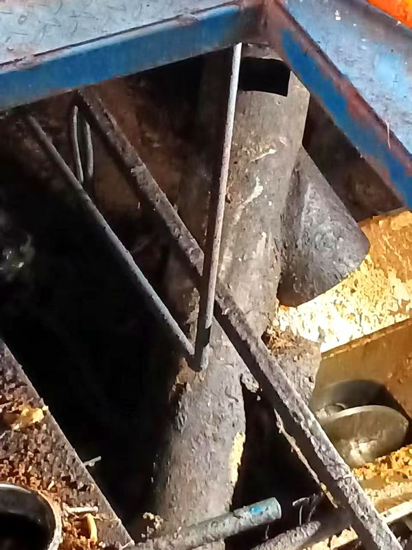
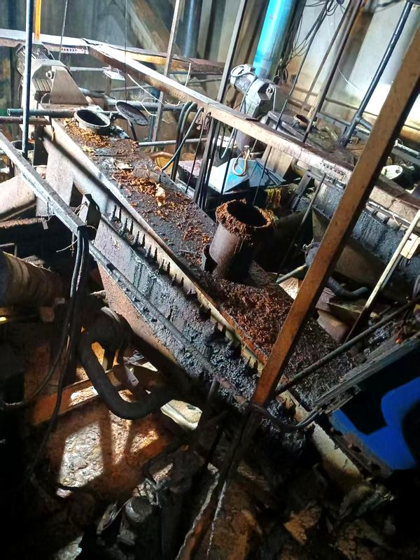
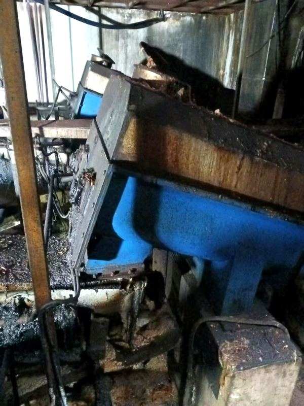
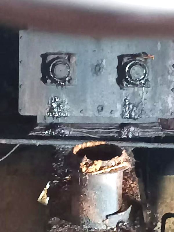
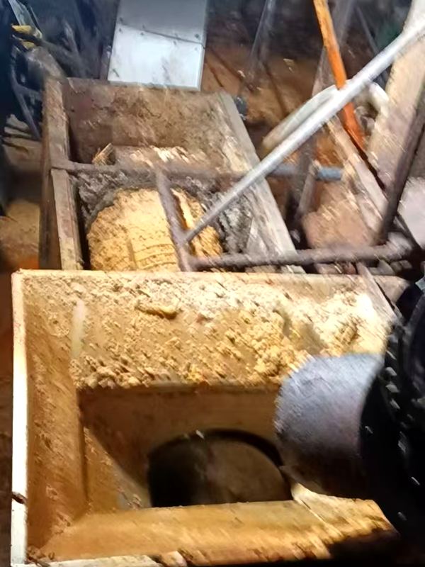
Based on the process flow diagram confirmed by your company: the segment "feed bin → twin-shaft dewatering screw → single-shaft dewatering screw → crusher → squeezer" is replaced by "hydraulic pulper → three-phase centrifuge". After the retrofit, no dewatering, crushing or pressing is needed; inorganic residue is drummed off-site for incineration, and grease is separated directly by the three-phase centrifuge. The existing cooking tank and dryer are reused, with no duplicate investment.
The problem with the existing line is not the downstream oil extraction but the upstream task of "shredding the feed". Treating food waste with two-stage dewatering screws plus crushing and pressing essentially follows the kitchen-wet-waste mindset: squeeze the water out first, then proceed. This route carries three unavoidable costs.
Compiled from on-site accounts and your process flow diagram. The upstream dewatering, crushing and pressing are within this retrofit scope; the filtrate tank, cooking tank and dryer are reused as-is and are out of scope.
| No. | Equipment / step | Current description | Issue |
|---|---|---|---|
| 1 | Feed bin | Material is manually pushed into the bin; ordinary discharge structure at the bottom | Requires a fixed post; labor-intensive |
| 2 | Twin-shaft dewatering screw | Two screws side by side, ~3.5 m long, trough with dewatering screen | Filtrate runs off; must be collected |
| 3 | Single-shaft dewatering screw | A single screw continues conveying and dewaters a second time | Further water loss; grease leaves with the water |
| 4 | Crusher | Separate crushing step that shreds the feed before the next stage | Plastic wrapping requires shutdown and cleaning |
| 5 | Squeezer | Screw pressing that expels excess water before discharge | Screw wears fast; press liquor is hard to treat |


The Zaozhuang client’s original line was the same as yours: large grab feeding, two-stage dewatering, crushing and pressing. After the retrofit the upstream stage was merged into hydraulic pulping and sorting; collection trucks simply tip the material from their bins directly into the feed hopper, and no dedicated feed-pushing post is needed.
Drawn from the process flow diagram confirmed by your company. Yellow is the original flow (dewatering + crushing + pressing); orange is the new flow after this retrofit (hydraulic pulping + three-phase centrifugation); dashed yellow boxes are facilities shared with the current plant and not newly built.
The left column is the current state and the right column is after retrofit. Every "saved" and "eliminated" corresponds to verifiable equipment sets, tonnage and electrical power.
| No. | Item | Current (dewatering + crushing + pressing) | After retrofit (hydraulic pulping) | Change |
|---|---|---|---|---|
| 1 | Feeding method | Material manually pushed into the bin, requiring a fixed post | Collection truck (or grab) tips directly; hydraulic feed at bin bottom, no dedicated feeder | Labor -2 / shift |
| 2 | Dewatering stage | Twin-shaft + single-shaft screws, two-stage dewatering, ~3.5 m or more in total | Dewatering stage removed; slurry is pulped in the main unit at the process concentration | Equipment -2 |
| 3 | Crushing step | Separate crusher; blades must be stopped and cleaned after plastic wrapping | Shredding is done once inside the pulper; on wrapping it reverses automatically | Equipment -1 |
| 4 | Press dewatering | Screw squeezer presses the material; press liquor collected separately | Pressing removed; slurry is pumped directly to three-phase separation | Equipment -1 |
| 5 | Process wastewater | Filtrate + wash water ~3 t/d, high COD; separate collection tank and treatment are mandatory | No process effluent discharged; process water recycled and topped up within the system | Wastewater eliminated |
| 6 | Impurity separation | After pressing, impurities are hand-picked; heavy impurities (grit, metal) easily damage the press screw | In-machine simultaneous separation: heavy impurities settle and discharge continuously; light impurities (plastic) are rejected continuously | No manual impurity sorting |
| 7 | Grease path | Dewatering and pressing carry part of the grease into the water phase; it is already lost before three-phase separation | Grease stays in the slurry phase throughout; no loss before three-phase separation | Oil yield ↑ |
| 8 | Equipment sets | Bin + twin-shaft screw + single-shaft screw + crusher + squeezer = 5 sets | Hydraulic pulper + feed pump + three-phase centrifuge = 3 sets | 5 → 3 |
| 9 | Footprint | Long in-line layout; the screw section takes up most of the building length | Main unit is compactly arranged; the former screw length can become storage or QC area | ~15 m of length saved |
| 10 | Odor control | Two-stage dewatering runs open; the filtrate tank is the main odor source | Fully enclosed operation; the main unit has a negative-pressure port that can connect directly to the existing odor system | Odor source eliminated |
| 11 | Wearing parts | Screw flights, dewatering screens and press screw wear fast; ~RMB 45,000/yr maintenance | Main unit is a single maintenance point; wearing parts are the knife set and screen; ~RMB 20,000/yr | Maintenance ↓RMB 25,000/yr |
| 12 | Power consumption | Dewatering 15 kW + dewatering 7.5 kW + crushing 22 kW + pressing 15 kW ≈ 59.5 kW | Pulping & sorting main unit 37 kW; net saving ~22.5 kW | Power -38% |
This is a full-line delivery of a similar retrofit project, with 18 panorama scenes you can switch through section by section. Press and drag on the image to look around 360°, scroll to zoom, and switch scenes by the labels at the bottom—— "no dewatering, no process wastewater" described above is exactly what the site looks like.
www.720yun.com/vr/16fjermv5u4Rated for a single 20 t/d line. Equipment is supplied as a set, including transport to site, installation, commissioning and training.
| No. | Equipment | Model / spec | Qty | Unit | Unit price (10k RMB) | Notes |
|---|---|---|---|---|---|---|
| 1 | Hydraulic pulper core unit | ZSGJ-3 (20 t/d class) | 1 | pc | 25.80 | Crushing, pulping and sorting in one; replaces dewatering, crushing and pressing in a single stage |
| 2 | Three-phase centrifuge new oil extraction | WLL-400 | 1 | pc | 32.70 | After heating, splits the slurry into oil, water and residue; the oil phase goes to the oil tank |
| 3 | Three-phase feed pump | G40-1 | 2 | pc | 1.10 | One duty, one standby; stable feed pressure |
| 4 | Slurry pump | ZJB-7.5 | 1 | pc | 1.40 | Positive-displacement pump conveying 8–12% solids slurry; resists clogging |
| 5 | Inorganic residue collection & drumming | Hopper + screw + dustbin | 1 | set | 1.80 | Plastic, bones and other inorganic residue discharged continuously, drummed off-site for incineration |
| 6 | Slurry piping & valves | DN100 quick-connect | 1 | set | 2.60 | Piping, valves and quick couplings from the main unit to the three-phase section; 304 stainless steel |
| 7 | Electrical control cabinet (extension) | Interfaced with the existing system | 1 | set | 3.80 | New main-unit and three-phase circuits and interlocks; existing control logic preserved |
| Equipment subtotal | 70.30 | |||||
| No. | Item | Spec | Qty | Unit | Amount (10k RMB) | Notes |
|---|---|---|---|---|---|---|
| 1 | Equipment positioning & foundation prep | — | 1 | item | 2.20 | Positioning, alignment and second-stage grouting of main unit, centrifuge and pumps |
| 2 | Piping, wiring & insulation | — | 1 | item | 1.90 | Slurry, hot-water and oil piping and electrical wiring, including pipe insulation |
| 3 | Commissioning, trial run & operator training | — | 1 | item | 1.70 | Water and loaded commissioning, parameter tuning; operation and maintenance training for 2 personnel |
| Engineering & service subtotal | 5.80 | |||||
| Replaced equipment | Spec | Original value (10k RMB) | |
|---|---|---|---|
| 1 | Twin-shaft dewatering screw | ~3.5 m, with dewatering screen | 15.50 |
| 2 | Single-shaft dewatering screw | With dewatering function | 9.80 |
| 3 | Crusher | Separate crushing step | 11.50 |
| 4 | Squeezer | Screw press dewatering | 17.80 |
| Original-value subtotal of old segment | 54.60 | ||
The tier is locked once on-site measured throughput is confirmed. The three tiers differ only in main-unit size and piping/valve diameters; the process route and works are identical.
| Capacity | Main unit model | Main unit | Centrifuge | Auxiliaries | Eng. & service | Total investment | Investment per (t·d) (10k RMB) |
|---|---|---|---|---|---|---|---|
| 10 t/d | ZSGJ-2 | 18.90 | 32.70 | 10.20 | 5.20 | 67.00 | 6.70 |
| 20 t/d recommended | ZSGJ-3 | 25.80 | 32.70 | 11.80 | 5.80 | 76.10 | 3.80 |
| 30 t/d | ZSGJ-4 | 31.60 | 32.80 | 12.90 | 7.00 | 84.30 | 2.81 |
Based on 20 t/d and 330 operating days per year, the annual benefit after retrofit is RMB 574,400, corresponding to a processing-cost reduction of RMB 87.0 per ton.
| Benefit item | Basis | 10k RMB/yr |
|---|---|---|
| Extra crude oil | Oil yield +0.6 pt → 39.6 t/yr × RMB 7,250/t | 28.71 |
| Electricity saving | Net 22.5 kW × 10 h/d × 330 d × RMB 0.65/kWh | 4.83 |
| Labor saving | 2 fewer staff × RMB 60,000/person·yr | 12.00 |
| Wastewater treatment fee | 990 t/yr × RMB 95/t | 9.40 |
| Maintenance & wearing parts | Annual maintenance 45,000 → 20,000 | 2.50 |
| Total annual benefit | 57.44 | |
| Assumption | Extra crude oil (t/yr) | Annual benefit (10k RMB) | Static payback (months) |
|---|---|---|---|
| +0.3 percentage points | 19.8 | 43.09 | 21.2 |
| +0.6 percentage points | 39.6 | 57.44 | 15.9 |
| +0.9 percentage points | 59.4 | 71.80 | 12.7 |
The key constraint is line shutdown time. All piping/valve prefabrication and electrical upgrade are done before shutdown; the on-site shutdown window is kept within 4 days.
| No. | Milestone | Time | Days | Content / key points |
|---|---|---|---|---|
| 1 | Site survey & plan confirmation | D1 – D3 | 3 | Confirm throughput, feed composition, existing controls and shutdown window |
| 2 | Equipment manufacture & delivery | D4 – D38 | 35 | Main unit and centrifuge 35 days; pumps, valves and controls in parallel |
| 3 | Pre-fabrication before shutdown (parallel with manufacture) | D10 – D16 | 7 | Piping/valve prefab, control-cabinet upgrade, foundation setting out; no production stop |
| 4 | Installation & tie-in | D39 – D42 | 4 | Shutdown window ≤4 days; tie into cooking tank and three-phase section |
| 5 | Water & loaded commissioning | D43 – D45 | 3 | No-load → water → loaded, gradually increasing load |
| 6 | Training & handover | D46 | 1 | Operation, maintenance and wearing-part replacement training |
Once the following information is provided, this plan can be upgraded from "comparison and estimate" to a "ready-to-sign technical agreement + fixed quotation".
| No. | Item | Requirements | Purpose |
|---|---|---|---|
| 1 | Throughput & composition | Daily average and peak feed over the last 3 months; moisture, oil content and impurity share | Confirm main-unit model and centrifuge capacity |
| 2 | Cooking-tank spare capacity | Existing cooking-tank volume, heating method and residence time | Confirm whether new slurry can feed in directly |
| 3 | Dryer spare capacity | Existing dryer throughput and required moisture content | Confirm whether all centrifuge residue can be handled |
| 4 | Existing controls | Installed capacity, main incomer specs, control mode (local/central) | Define the control extension scope |
| 5 | Inorganic residue route | Whether incineration or off-site disposal qualification exists; daily output | Verify the drumming, transport and incineration chain |
| 6 | Shutdown arrangement | Acceptable shutdown days and time window | Lock the 4-day tie-in window |